Lakosa MDS-800 / CP/M Diskettenimages aus RWA auf Floppydisk schreiben. (2019/10/22)
Leider sind es RAW.IMG Dateien, also nicht mit IMD oder ähnlich zu nutzen da sämtliche Informationen für das Format fehlen.
Programme wie rawrite, duit, diskimage können nicht mit den 26Sektoren x 256bytes umgehen und sind auf MSDOS like
512bytes Sektorgröße beschränkt.
ebenfalls interessant: http://www.vcfed.org/forum/showthread.php?67511-CPM-on-MDS225-system-generation
IMD sollte mir helfen können.
Aus dem VFCED habe ich folgenden Hinweis auf BIN2IMD bekommen.
Ich habe das selber schon mal probiert, war aber nicht erfolgreich.:
Hier der passende Ausschnitt aus dem Manual
Befehlszeile:
bin2imd. cpm2.img lak-cpm2 /1 c=@cpm2.txt n=77 DM=3 SS=256 SM=1-26 /v1
bin2imd cpm2.img Quelldatei lak-cpm2 Zieldatei
/1 1 Seite
c=@cpm2.txt Datei mit Beschreibungstext für IMD
n=77 77 Track (zylinder)
DM=3 500kbps (track data mode)
SS=256 Sectorgröße 256 bytes (sector size)
SM=1-26 Sektornummerierung von 1 bis 26 (sector numbering map)
/v1 Ausgabe zum Programmablauf
Mit ein wenig Glück gibt es keinen skew oder sectortranslation, so dass es etwas einfacher ist.
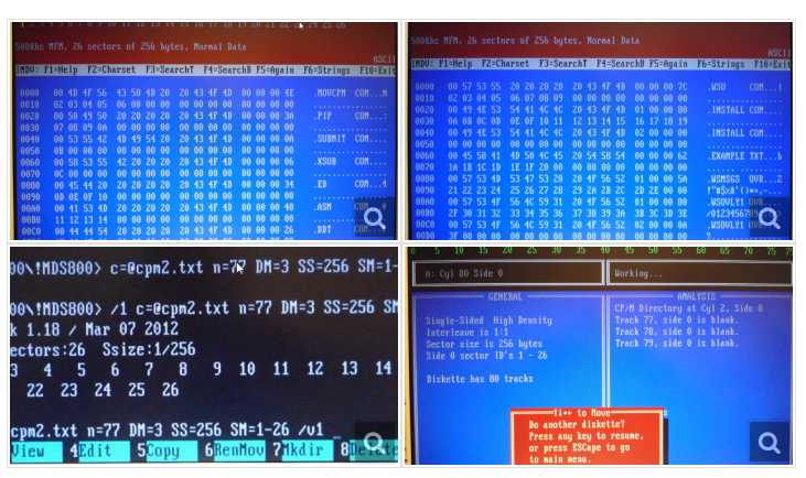
D:\DSKIMAGE\MDS-800\!MDS800>wsv3.img c=mds-800_ws-v3 /1 /u n=77 DM=3 ss=256 sm=1
BINary-2-IMageDisk 1.18 / Mar 07 2012
0/0: Mode:3 Sectors:26 Ssize:1/256
Smap: 1 2 3 4 5 6 7 8 9 10 11 12 13 14 15 16 17 18
19 20 21 22 23 24 25 26

ANHANG:
BIN2IMD
Hier der passende Ausschnitt aus dem Manual:
Use: BIN2IMD binary-input-file IMD-output-file [option-file] [options]
Use: BIN2IMD input-file output-image [option-file] [options]
opts: /1 - 1-sided output
/2 - 2-sided output
/C - write Compressed sectors
/U - write Uncompressed sectors
/V[0|1] - Verbose output
C=text | @file - image Comment
N=#cylinders - set Number of output cylinders
DM[s]=0-5 - track Data Mode
SS[s]=128-8192 - track Sector Size
SM[s]=n[,n-n][n.#] - track Sector numbering Map
CM[s]=n[,n-n][n.#] - track/sector Cylinder Map
HM[s]=n[,n-n][n.#] - track/sector Head Map
SM=1-9 <= Both sides
SM0=1-9 <= Side0 only
SM1=1-9 <= Side1 only
It is therefore possible to create disks which are formatted differently on one side than the other (Most commonly used for
formats which require differing sector numbering and/or head mapping on
each side).As a minimum, in order to generate an image, BIN2IMD needs
at least the following options applied to all sides that are being
generated:
#ImageDisk Page: 34
DM= sets the Data Mode, which must be one of:
0 = 500 kbps FM \ Note: kbps indicates transfer
1 = 300 kbps FM > rate, not the data rate,
2 = 250 kbps FM / which is 1/2 for FM
3 = 500 kbps MFM encoding.
4 = 300 kbps MFM
5 = 250 kbps MFM
SS= sets the Sector Size, and must be one of:
128, 256, 512, 1024, 2048, 4096 or 8192.
SM= specifies the Sector Numbering Map, which also defines the number of sectors occuring on a track. SM= may consist of any
of the following elements:
number = Single sector-number
number1-number2 = Series ranging from number1 to number2
number.times = Single value occuring multiple times.
Multiple elements may be combined into a map by separating them with commas:
SM=1,2,3,4,5,6,7,8,9 <= 9 sectors from 1 to 9
SM=1-9 <= Also 9 sectors from 1 to 9
SM=9-1 <= 9 sectors from 9 to 1
SM=1,2-8,9 <= 9 sectors from 1 to 9
SM=1.9 <= Sector #1 occuring 9 times **
** This (1.9) is actually invalid since sector numbers may occur once within a track, however this format is useful in some of the other lists.
The sector mapping you specify MUST match the order in which the sector data occurs in the binary file. If you wish to
create images with differing interleave etc. You must first create the image with the pysical data ordering, and then use
the IMDU utility to re-interleave it.
HM= specifies a non-standard Head Numbering Map (if not specified, all sectors are assumed to have the physical head
number encoded). The number of HM= entries must match the number of sectors defined by SM=.
Here is an example where a disk is created which logicaly has 20 sectors on Side0, even though they are physically organized
as sectors 1-10 on Side0, and 11-20 on Side1:
SM0=1-10 HM0=0.10 SM1=11-20 HM1=0.10
NOTE: The HM0=0.10 isn't strictly necessary, since the default head encoded for Side0 would be 0, however it has been included
for it's descriptive value.
CM= specifies a non-standard Cylinder encoding. Very rarely used, this option operates similarly to HM=.
ImageDisk Page: 35
The /1 and /2 options are rarely used. These options exist to inform BIN2IMD that a disk is single or double sided in caseswhere it may not be able to determine this from the parameters./2 can be used when both sides are the same, and no Side1 specific options have been specified - Use /2 to let BIN2EXE
know that it should generate two sides (You could also just specify one Side1 specific option as the presence of such an
option automatically sets double-sided).
/1 or /2 are also used in option files, when the number of sides to be encoded changes part way thorugh the disk. An
example of this might be a disk which has system tracks on Side0 only for the first two Cylinders, and is double-sided
after that. This is quite rare.
/V controls the output of Verbose information detail about the diskette format being generated.
/V = Generate track format summaries only
/V0 = Generate no detail (Default - use this to turn Verbose detail output OFF within an option file).
/V1 = Generate detail showing track format and map detail.
C= Specifies a comment to be included in the image. A single line of text can be specified. To accomodate the fact that you
cannot put spaces in comamnd line parameters, any '~' characters occuring in the comment text will be translated to
spaces. You may also include the content of a file with 'C=@filename' - in this case the text file is included with no
translation.
11.1.2 Mixed format disks - Command option files
BIN2IMD can create mixed format disks - those in which the format changes from one track to the next. To do this, you mustspecify the command options to specify the format into an "option" file (type: .B2I), with each set of parameters on a
separate line preceeded by the Cylinder number where those parameters are to take effect.
You may also use a command option file to establish commonly used initial format option. If the first entry in the file is
assigned for Cylinder 0, then these options need not be specified on the command line.
Blank lines, and lines beginning with ';' are ignored as comments in the command option file.
;
; Example command option file to demonstrate a 40 Cylinder
; double-sided disk which is formatted 10x256 bytes sectors
; at 250kbps FM on the first two Cylinders, and 10x512 byte
; sectors at 250kbps MFM on the remaining 38 Cylinders.
;
0 N=40 DM=2 SS=256 SM=1-10 /2
2 DM=5 SS=512 SM=1-10 /2
ImageDisk Page: 36 ....
Danke an alle die mitgeholfen haben.